Steering angle kit
Developing a steering angle kit by ourselves was not just due to the reason that we couldn't buy one that would give the car reliable 65° angle on both sides with our desired alignment specifications. It was also an exciting topic for Flo, who studied automotive engineering back in the days, where he could turn theoretic knowledge into something useful.
Alex felt the need of a new steering angle kit, as she couldn't keep up with the competition. As judges would mostly complain about her not being aggressive enough on the throttle, they refused to believe the car would actually spin by staying or getting too hard on the throttle. The old steering angle kit's limit was at somewhat 45°, which turned out to be not enough to be competitive with an agressive driving style. Sometimes it is the driver's capabilities, which are preventing better drifting, but there are also occasions in which actually the driver is hold back by the car's capabilities.
How do you get a project like this started?
The cheapest and easiest way to gain more angle are so called cut knuckles. You cut away the tie rod connecting point, remove material between the knuckle itself and the tie rod connecting point and weld it back together. While this approach sounds easy you have to ensure that the knuckle geometry after welding is exactly the way it should be. Otherwise you easily run into problems with one side steering way more/or less than it should or even worse you create binding issues, where the steering goes to full-lock and you are not able to steer it back.
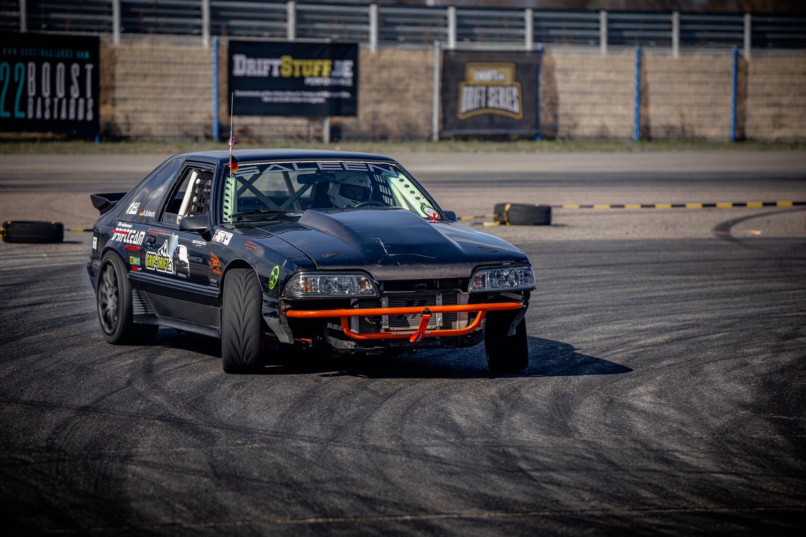
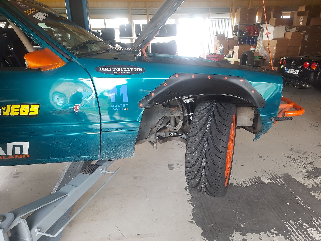
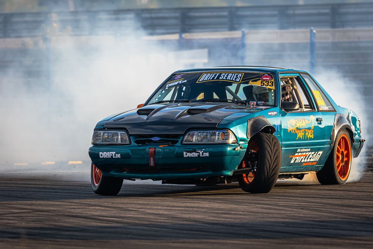
Notice the visible difference in steering angle between both sides
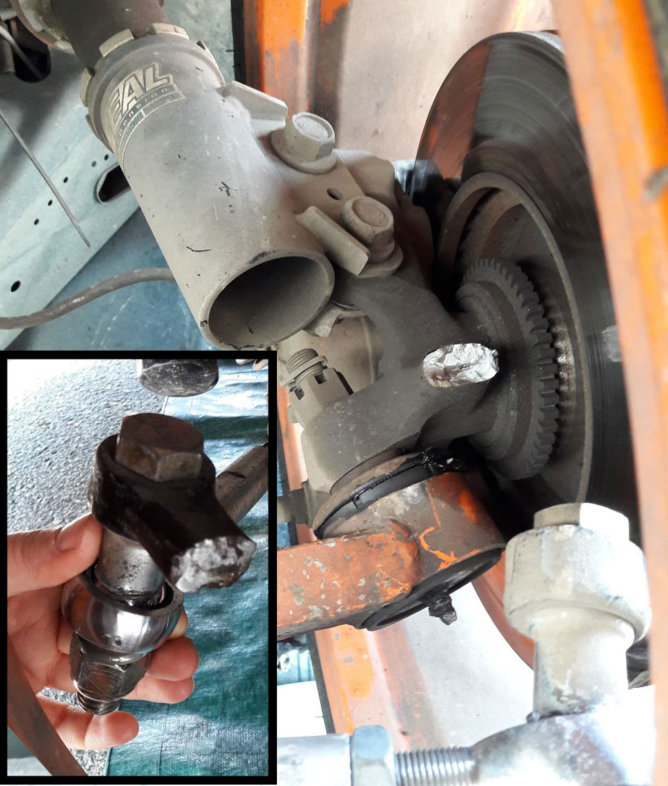
With the old steering angle kit the steering angle was limited to around 45°. At higher steering angle the tie rod adjuster would touch the lower control arm, without a bump stop this will cause damaged parts. Fox actually had two steering knuckles break at the welds. Rewelding the steering knuckles caused deviations in the geometry.
If you want full control over the characteristics of your steering angle kit, the best way to move forward is to set up a 3D model, simulate the steering behavior, verify it with 3D printed prototypes and then have billet parts made by a cnc machine.
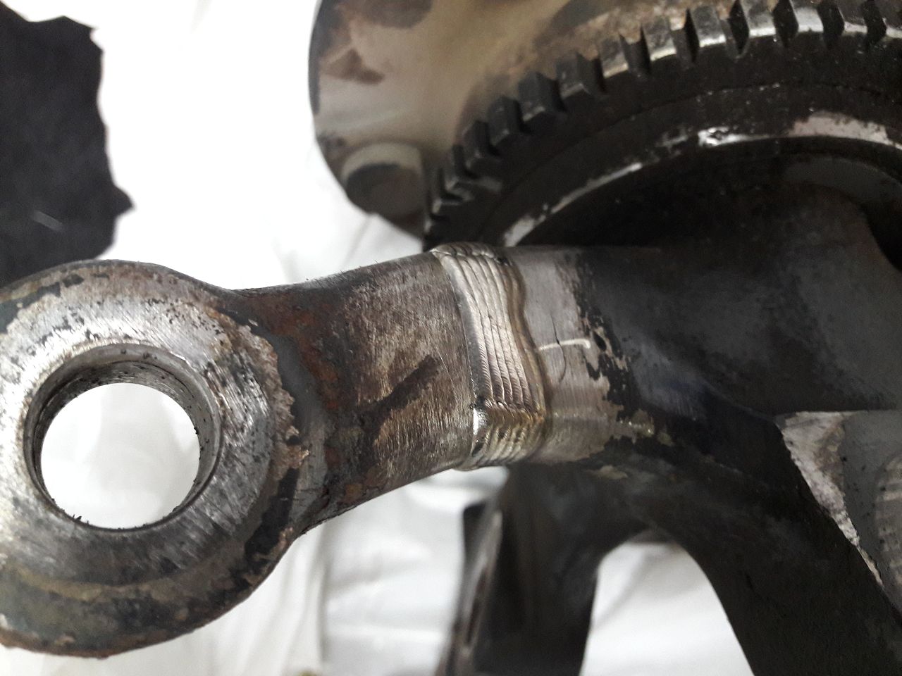
rewelded cut knuckle
Why is a redesigned Lower Control Arm necessary?
More steering angle usually requires a much wider front track width and modified control arms, otherwise the wheels collide with the car’s frame or the control arm. Modified control arms are usually longer to increase track width and are shaped to avoid collisions. Wider control arms should be combined with adjustable suspension top mounts in order to adjust camber and caster.

3d-printed control arm prototype
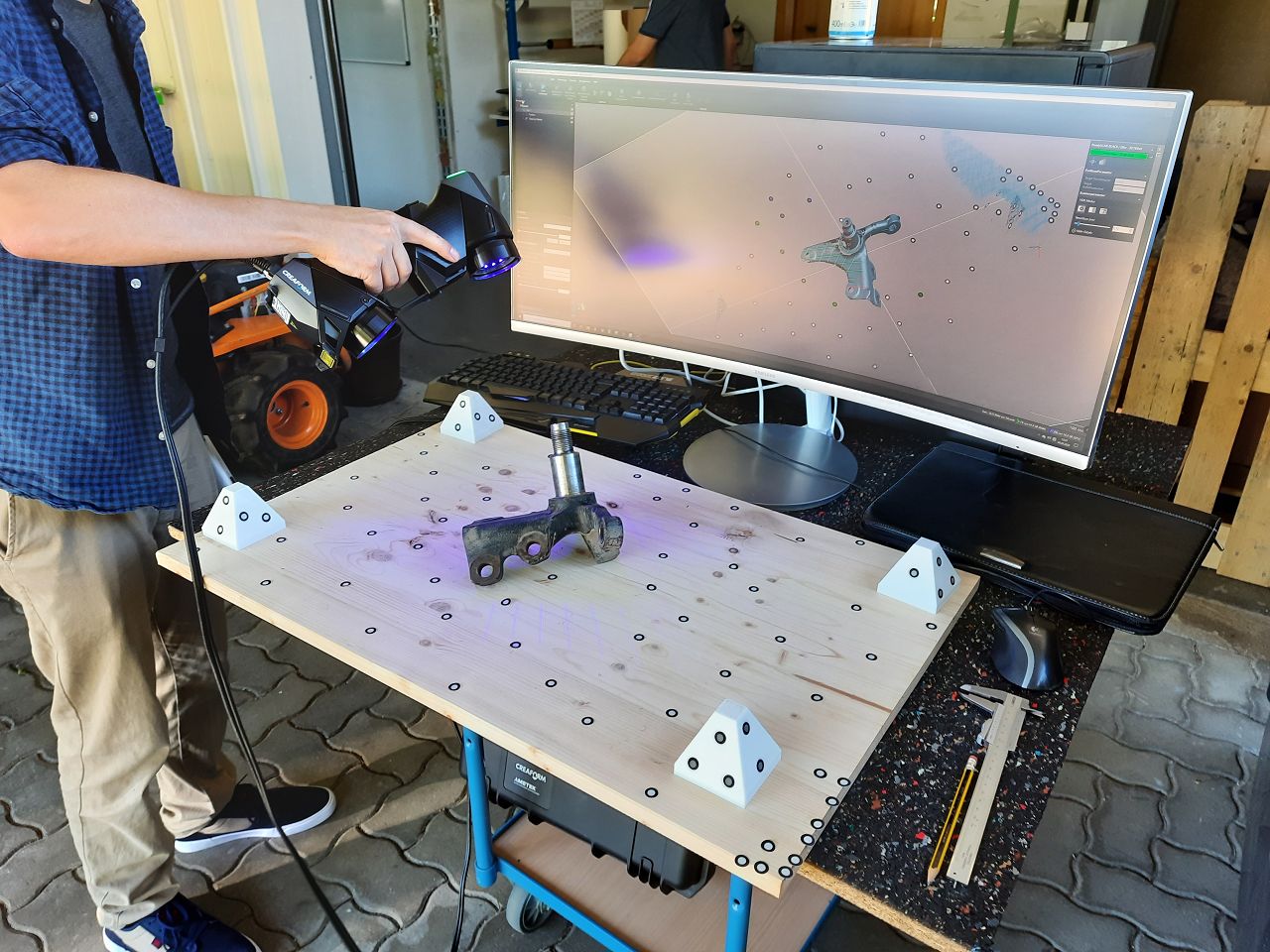
3d-scanning the OEM knuckle
How do you build a new steering knuckle from scratch?
Being involved with 3D printing for many years now, 3D scanning is a familiar process for reverse engineering. 3D scanning the original steering knuckles gave us a digital 3D model including all the relevant geometry. For example the measurements for the brake caliper mounts and suspension mounts, as well as wheel hub mounts, we got the data we needed with one scan.
This 3D model is the starting point for the development of our own custom steering kit with the following targets;
- 65° of steering angle in both directions
- adjustable Ackermann
- reliable and easy to maintain
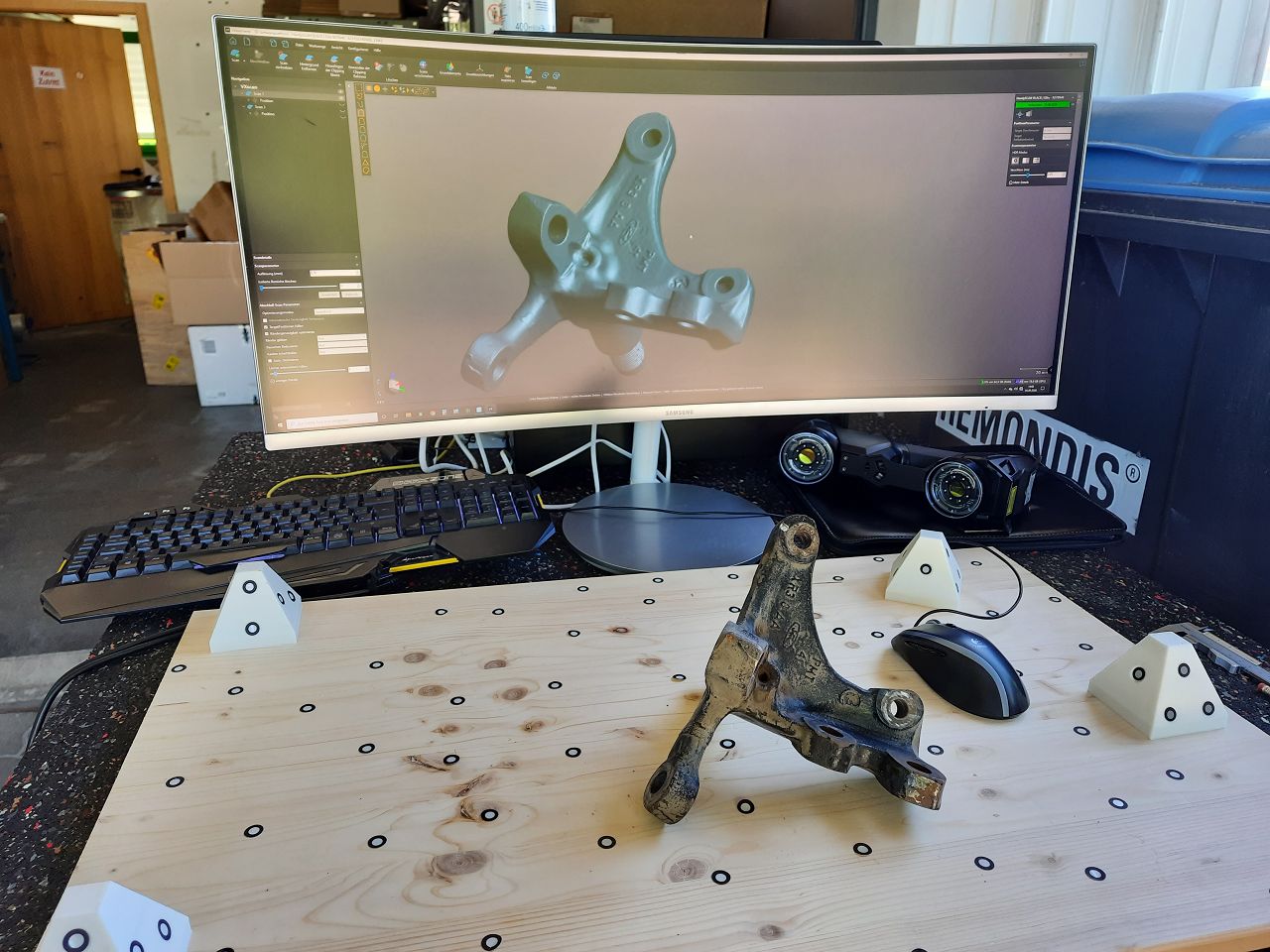
OEM knuckle and it's digital twin
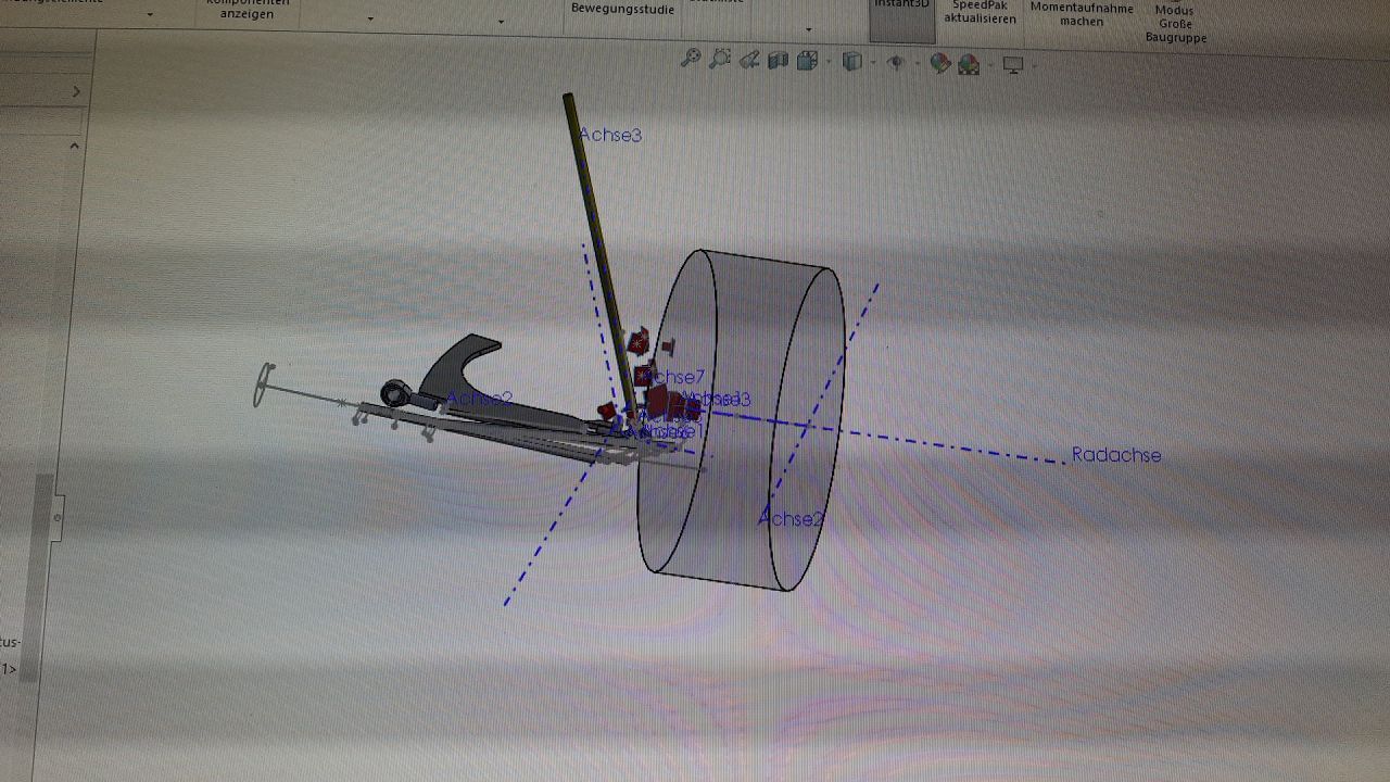
Design, Print, Mount, Repeat
In order to reach the targets, we took some more measurements of the car and setup a 3d model of the front axle. This allowed us to simulate different knuckle designs before prototyping/3d printing the optimized design.
3d printing
Maching a billet part from stainless steel is rather expensive, so we wanted to make absolutely sure that the design was working. For that purpose we 3d printed our optimized design in order to install it on the car and verify that our 3d model matches the real world.
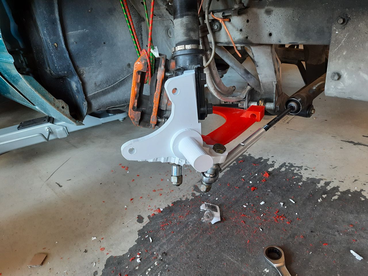
Testfitting the 3d printed knuckle and control arm allowed us to measure the steering angle on both sides as well as the Ackermann behavior.
cnc milling
After we verified the final design with the 3d-printed prototypes we were confident enough to order CNC-machined knuckles and control arms.
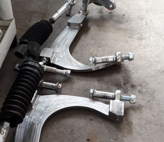
The control arms are a simple design, the general shape was cut out with a waterjet machine and then milled down on a CNC.
The steering knuckles are a far more complex design and were machined on a 5-axis CNC machine.
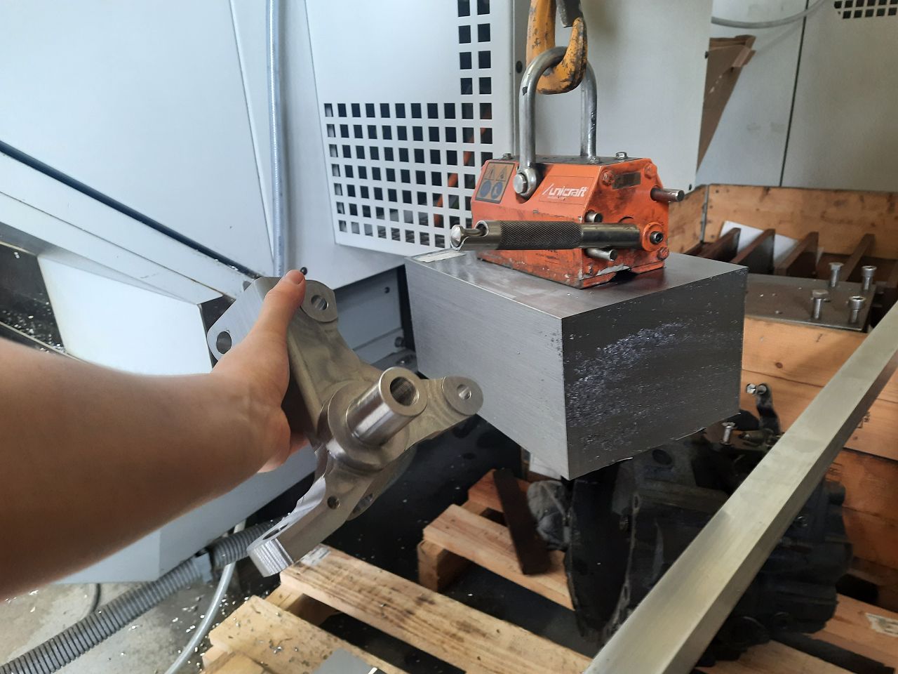
left: knuckle after machining, right: knuckle before machining
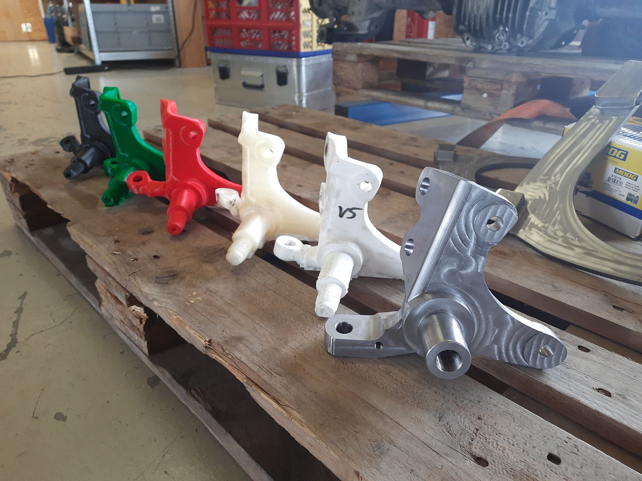
Iterations to the perfect design: Several 3D-printed designs were test-fitted on the car, before the way more expensive billet parts were ordered.
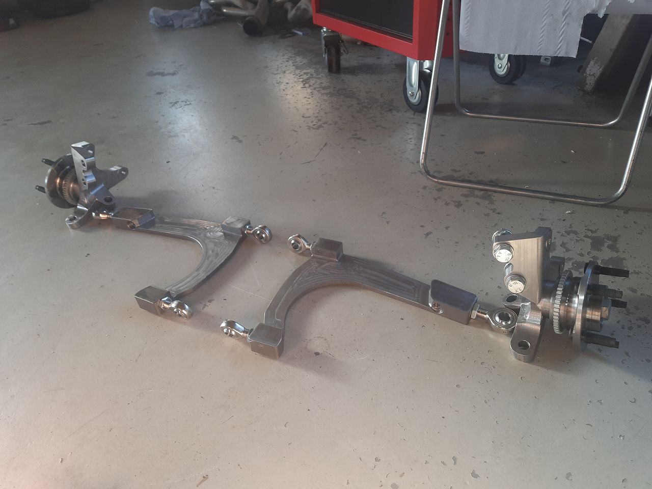
billet control arms and knuckles before first installation
Test drifting the new steering angle kit
We were very excited to give the new steering angle kit a try. Unfortunately the first euphoria didn't endure long, because the Saleen did what especially he is good in: breaking parts.
We came to realize that 10mm of steel is not enough material to withstand drift forces. Although Alex drove just two small circles sideways without being in full angle, it put so much force on the LCA, that it bent.

Adjusting the LCA
The second version of the LCA was made with 35mm thick steel reinforcement.
Several drift events and rough competitions later - no breaking or bending so far! But we also have to mention we installed the new version into Fox and not Saleen, so the ultimate endurance test still lies ahead.
